14. These preliminaries over, we will pass on to the solution of a number of successive problems, which fulfil the double object of exercising us in the method of projections and make it possible for us to make further progress in descriptive geometry.
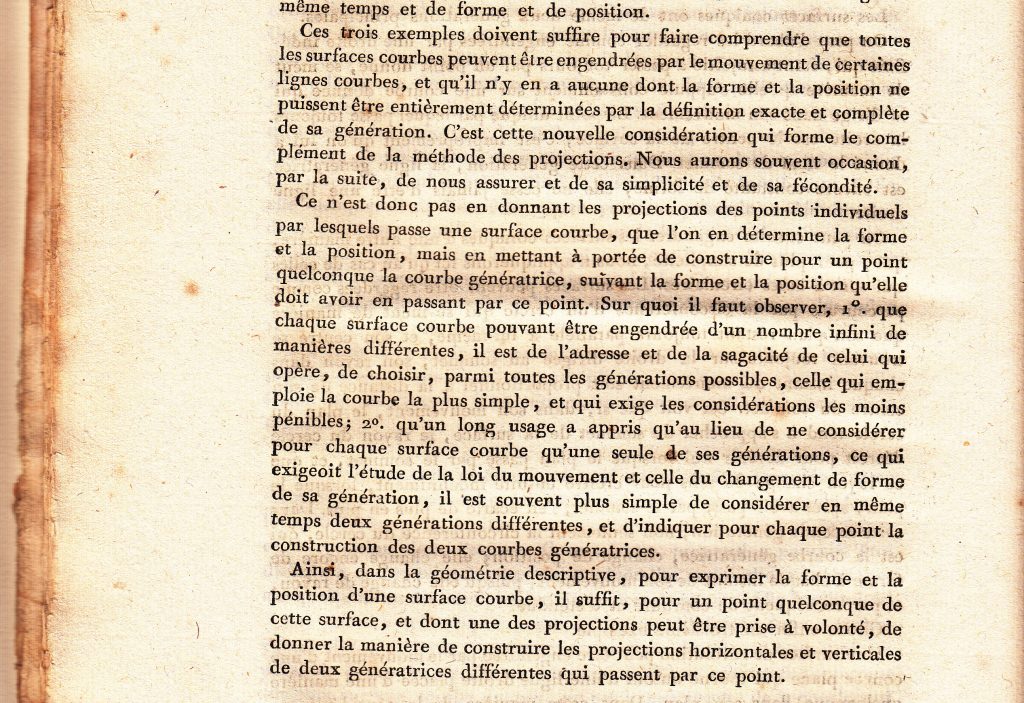
First question. Being given (Fig. 4) the projections of a point, D, d, and the projections of a line AB and ab, construct the projections of a second line passing through the given point and parallel to the first line.
Solution. The two horizontal projections of the given line and the required line must be parallel for they are the intersections of two vertical parallel planes with the same plane. Furthermore, the required line passing through the given point, its projections must be respectively pass through the same point. Therefore, if through the point D one takes EF parallel to AB and if through the point d one takes ef parallel to ab, the lines EF and ef will be the required projections.
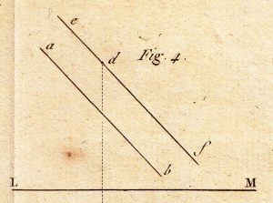
15. Second question. Being given (Fig. 5) the traces of a plane AB, BC and the projections of a point, G, g, construct the traces of a second plane passing through the given point and parallel to the first plane.
Solution. The traces of the required plane must be parallel to the respective traces of the given plane, because these traces, considered in pairs, are the intersections of two parallel planes with the same plane. It only remains, therefore, to find for each of them the point through which the line passes. For this, through the given point conceive a horizontal line which will be in the required plane; this line will be parallel to the trace AB and it will cut the vertical plane in a point which will be one of those of the trace of the required plane on the vertical plane; and one will have its two projections leading through the point g on the horizontal gF, and through the point G of the line GI, parallel to ab. If one produces GI as far as where it meets LM, the intersection of the planes of projection, in a point I, this point will be the horizontal projection of the intersection of the horizontal line with the vertical plane. Therefore, this point of intersection will be on the vertical IF passing through the point I. But it must also be on the vertical gF; thus it will be at F, the point of intersection of the two last lines. Therefore, lastly, if through the point F one makes a parallel to BC it will be, on the vertical plane, the trace of the required plane; and, if after producing this trace to meet LM in point E, one draws ED parallel to AB, one will have the trace of the same plane on the horizontal plane.
Instead of imagining on the required plane a horizontal line, one could imagine a parallel to the vertical plane which, by similar reasoning, will give the following construction:-
One will draw through the point G and parallel to LM, the line GD; through the point g one will take gH parallel to CB; and one will produce it to cut LM in point H, through which one makes HD perpendicular to LM; this last line will cut GD in a point , through which, if one takes a parallel to AB, one will have one of the required traces, and if, after producing this trace to meet LM in point E, one draws EF parallel to BC, one will have the trace on the vertical plane.
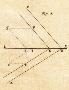
16. Third question. Being given (Fig. 6) the two traces of a plane AB, BC, and the projections of a point D, d, construct (i) the projections dropped perpendicularly from the line to the plane, (ii) that of the point of meeting of the line and the plane.
Solution. The perpendiculars DG, dg, dropped from the points D and d on the respective traces of the plane, will be the projections of the required line; for if through the perpendicular one imagines a vertical plane, this plane will cut the horizontal plane and the given plane in the two lines which will be both perpendicular to the common intersection of these tow planes, AB; but, the first of these lines, being the projection of the vertical plane, is also that of the perpendicular which it contains; thus, the projection of this perpendicular line passes through the point D and is perpendicular to AB.
The same demonstration holds good for the vertical projection. As to the point of meeting of the perpendicular and of the plane, it is evident that it must be on the intersection of this plane with the vertical plane taken through the perpendicular; an intersection which is projected on EF. If one has the vertical projection fe of this intersection, it will contain the required point and, because this point must also be projected on the line dg, it is at the intersection g of the two lines fe and dg. It only remains, therefore, to find the line fe; but the intersection of the given plane with the vertical plane is perpendicular with it, meeting the horizontal plane in point E; thus one will have the vertical projection e, in dropping Ee perpendicularly onto LM; and it meets the vertical plane of projection in a point of which the horizontal projection is the intersection F of the line LM with DG, produced if necessary, and of which the vertical projection must be on the vertical Ff and on the trace CB; it will, therefore, be at the point f of their intersection.
The vertical projection f of the foot of the perpendicular being found, it is easy to construct the horizontal projection; for if one drops onto LM the perpendicular gG, this line will contain the required point, but the line DF must also contain it; therefore it will be at point G, the intersection of the two lines.
17. Fourth question. Being given (Fig. 7) the two projections of a line, AB and ab, and the projections of a point, D, d, construct the traces of the plane which passes through the point perpendicularly to the line.
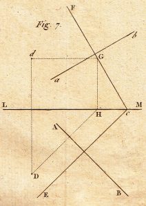
Solution. One knows already, from the preceding question, that the two traces must be perpendicular to the respective projections of the two lines. It remains to find, for each of them, one of the points through which it must pass. For this, if through the given point one imagines, in the required plane, a horizontal produced to meet the vertical plane of projection, one will have its vertical projection passing through the point d of a horizontal dG, and its horizontal projection passing through point D a perpendicular DH to AB, produced to cut LM in point H, which will be the horizontal projection of the point of meeting between the horizontal with the vertical plane of projection. This meeting point, which must be found in the vertical HG and in the horizontal dG, and consequently at the point G of intersection of the two lines, will be thus one of the points in the trace of the vertical plane; therefore one will have this trace by taking the line FC through point G and perpendicular to ab; finally, if through the point C, where the first trace meets LM, one takes CE perpendicular to AB, one will have the second required trace.
If the question was to find the meeting point of the planes with the line, one woud operate as in the preceding question.
Lastly, if it is necessary to drop a perpendicular from the given point to the line, one will construct, as we have just said, the meeting of the line with the plane taken through the given point and which is perpendicular to it; and one will have, for each of the two projections of the required perpendicular, two points through which it must pass.
18. Fifth question. The position of two planes being given (Fig. 8) by means of their traces, AB and Ab for one, and CD and Cd for the other, construct the projections of the line in which they intersect.
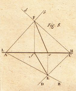
Solution. All the points of the trace AB are on the first of the two given planes, and all these of the trace CD are on the second. E, the point of intersection of the two traces, is evidently on both planes; it is, consequently, one of the points on the required line. One seeks, likewise, F, the point of intersection of the two traces in the vertical plane, which is another point on this line. The intersection of the two planes is, therefore, located, in that it meets the horizontal plane in E and the vertical plane in F.
Thus, if one projects point F to the horizontal plane, by dropping the perpendicular Ff onto LM, and if one draws the line fE, this will be the horizontal projection of the intersection of the two planes. Likewise, if one projects the point E onto the vertical plane, by dropping the perpendicular Ee onto LM, and if one draws the line eF, this will be the vertical projection of the same intersection.
19. Sixth question. Two planes (Fig. 9) being given by their traces, AB and Ab for the first, and CD and Cd for the second, construct the angle formed between them.
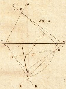
Solution. After having constructed, as in the preceding question, the horizontal projection Ef of the intersection of the two planes, if one imagines a third plane which is perpendicular to them, and which is consequently perpendicular to their common intersection, this third plane will cut the two given planes in two lines, which will contain between them an angle equal to the required angle.
Furthermore, the horizontal trace of this third plane will be perpendicular to the projection Ef of the intersection of the two given planes, and it will form with the two other lines a triangle, the angle of which, opposite to the horizontal side, will be the angle required. It is only necessary to construct this triangle.
But it is immaterial through which point in the intersection of the two first planes the third plane passes; one can thus assume its trace at pleasure on the horizontal plane, provided that it is perpendicular Ef. Taking, therefore, any line GH, perpendicular to Ef, terminated at G and H on the traces of the two given planes and which meet Ef in a point T, this line will be the base of the triangle to be constructed. Actually, let us imagine that the plane of the triangle turns about its base GH, like a hinge, into the horizontal plane; in this movement, its apex, which is originally in the intersection of the two planes, does not leave the vertical plane taken through this intersection, because the vertical plane is perpendicular to GH; and when the plane of the triangle is revolved flat, this apex is on the one of the points of line Ef. Thus, it only remains to find the height of the tirnalge or the length of the perpendicular dropped from point I to the intersection of the two planes.
But this perpendicular is comprised of Ef in the verical plane. If one imagines that this plane is turned about the vertical fF and is applied to the vertical plane of projection, and if one carries fE from f to e, fI from f to I, the line eF will be the length of the part of the intersection between the two planes of projection; and if from the point i, one drops to this line a perpendicular ik, this will be the height of the triangle required.
Therefore, finally, carrying ik from I to K and achieving the triangle GKH, the angle at K will be equal to the angle formed by the two planes.
20. Seventh Question. Two lines which intersect in space (Fig. 10) being given by their horizontal projections AB and AC, and by their vertical projections ab and ac, construct the true angle between them.
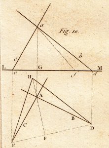
Before proceeding to the solution, we will notice that since the two given lines are supposed to intersect, the point A of their horizontal projections and the point a of their vertical projections will be the point in which they cut and will lie, consequently, in the same line aGA perpendicular to LM. If the two points A and a were not on the same perpendicular to LM, the given lines could not intersect and so could not be in the same plane.
Solution. One will imagine the two given lines produced to meet the horizontal plane, each in a point, and will construct these two points of meeting. To do this one will produce the lines ab, ac until they cut LM in two points d, e, which will be the vertical projections of these two points; through the points d,e, one will take, in the horizontal plane and perpendicular to LM, two lines dD, eE, which by passing each through one of these points, will determine their positions through their intersections D, E with the respective horizontal projections AB, AC, produced if necessary.
This done, if one leads the line DE, this line and the two parts of the given lines between their point of intersection and the points D, E, form a triangle, whose angle opposite to DE will be the required angle. Thus it is only necessary to construct this triangle. For this, after having dropped from point A a perpendicular, AF to DE, if one iagines that the plane of the triangle is turned about its base DE, like a hinge, until it is laid down ontot he horizontal plane, the apex of this triangle, during its movement, will not emerge from the vertical plane taken through AF, and will lie on FA produced to H, the distance of which from the base DE remains to be found.
But the horizontal projection fo this distance ti the line AF, and the vertical height of one of its extremities above the other is equal to aG. Therefore, by virtue of Fig. 3, if on LM one carries AF from G to f, and if one takes the hypotenuse af, this will be the required distance. Thus, lastly, if one transfers af from F to H, and if through H one takes the two lines HD, HE, the triangle is constructed and angle DHE will be the angle required.
21. Eighth Question. Being given the projections of a line and the traces of a plane, find the angle formed between the line and the plane.
Solution. If through a point taken on the given line, one imagines a perpendicular to the given plane, the angle formed between this perpendicular and the given line will be the complement of the required angle, and it is sufficient to find this angle to resolve the question.
But, if on the two projections of the line, one takes two points which will lie in the same perpendicular to the intersection of the two planes of projection, and if through these two points one takes perpendiculars to the respective traces of the given plane, one will have the horizontal and vertical projections of the second line. The question will thus be reduced to constructing the angle formed by two lines which intersect, and will return to the preceding case.
22. When one proposes to map a country one usually imagines a series of lines through particular points which form a number of triangles, and then one reproduces these triangles on a chart to a very small scale, placing the triangles in the same order as those they represent. The operations which are necessary on the land itself consist principally of the measurement of the angles of these triangles, and so that these angles can be reproduced on the chart, they must be angles in the horizontal plane, i.e. parallel to those of the chart. If the plane of the angle is oblique to the horizon, it is not the angle itself which must be reproduced, but its horizontal projection; and it is always possible to find this projection when, after having measured the angle itself, one has moreover measured the angles which the two sides form with the horizontal. This is given in the following operation and is known as the reduction of an angle to the horizontal.
Ninth Question. Being given the angle formed by two lines and the angles which each form with the horizontal plane, construct the horizontal projection of the first of these angles.
Being given the angle formed by two lines and the angles which each form with the horizontal plane, construct the horizontal projection fo the first of these angles.
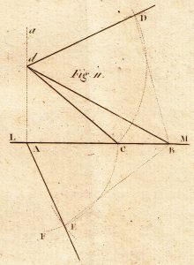
Solution. Let A’ (Fig. 11) be the horizontal projection of the apex of the angle required, and AB be that of one of its sides, so that the other side AE can be drawn later. One will imagine that the vertical plane of projection passes through AB, and having taken through point A a vertical Aa of indefinite length one will take on it, at pleasure, a point d, which can be regarded as the vertical projection of the apex of the observed angle. That done, if through the point d one takes the line dB which makes with the horizontal an angle dBA equal to that of the first side with the horizon, B will be the meeting point of the side with the horizontal plane. Likewise, if through the point d one takes the line dC, which makes with the horizontal an angle dCA equal to that of the second side with the horizon, and if from the point A as centre, with the radius AC, one describes an arc of a circle CEF, the second side can meet the horizontal plane only in one of the points of the arc CEF. It is necessary only to find the distance of this point from some other point such as B.
But this last distance is in the plane of the angle observed. If therefore, one takes the line dD, such that the angle DdB will be equal to the observed angle, and if one transfers dC from d to D, the line DB will be equal to this distance.
Thus, if with the point B as centre, and radius equal to BD, one describes an arc, the point E where it cuts the first arc CEF will be the point at which the second line meets the horizontal plane; therefore, the line AE will be the horizontal projection of this side and the angle BAE, that of the observed angle.
The nine preceding questions are sufficient to give an idea of the method of projections; they cannot demonstrate all its uses. But to appraise these we will rise to considerations more general, and we will see the operations which will be more appropriate to fulfill this object.